The part geometry lessons below review basic geometry concepts that are regularly used in
part design. These concepts include 2D and 3D shapes, part envelopes and cross-sections, and
feature types such as holes, ribs, and gussets.
|
Part Shapes |
Part Features |
 Part Parameters |
Part Shapes
2D Shapes
A 2-dimensional shape can be defined as a flat surface contained within a closed boundary. A 2D shape has length and width, but no height. While real-world parts are defined as 3D shapes, an understanding of 2D shapes is equally important. When designing a part, 2D shapes are used as part surfaces, cross-sectional surfaces, and projected surfaces. These concepts will be explored later in the lesson.
One type of 2D shape is that formed by a curved boundary, such as the following:
2D shapes formed by a boundary of straight lines are called polygons and can have any number of sides.
If all sides are of equal length and separated by equal angles, the shape is called a regular polygon.
If all interior angles of the polygon are less than 180 degrees, it is defined as convex. Otherwise, the polygon is concave. All regular polygons are convex.
A 2-dimensional shape can be defined as a flat surface contained within a closed boundary. A 2D shape has length and width, but no height. While real-world parts are defined as 3D shapes, an understanding of 2D shapes is equally important. When designing a part, 2D shapes are used as part surfaces, cross-sectional surfaces, and projected surfaces. These concepts will be explored later in the lesson.
One type of 2D shape is that formed by a curved boundary, such as the following:
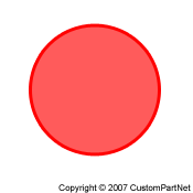
Circle |
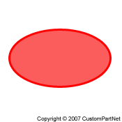
Ellipse |
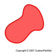
Irregular |
2D shapes formed by a boundary of straight lines are called polygons and can have any number of sides.
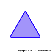
Triangle |
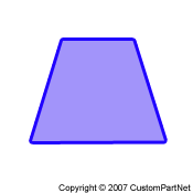
Quadrilateral |
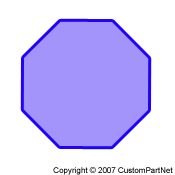
Octagon |
If all sides are of equal length and separated by equal angles, the shape is called a regular polygon.
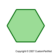
Regular hexagon |
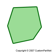
Irregular hexagon |
If all interior angles of the polygon are less than 180 degrees, it is defined as convex. Otherwise, the polygon is concave. All regular polygons are convex.
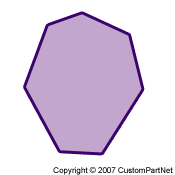
Convex polygon |
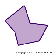
Concave polygon |
3D Shapes
A 3-dimensional shape is a solid object which is bound by several connected surfaces. A 3D shape has length, width, and height. The surfaces of some simple 3D shapes are all polygons, as shown below.
Other basic 3D shapes include curved surfaces.
A 3-dimensional shape is a solid object which is bound by several connected surfaces. A 3D shape has length, width, and height. The surfaces of some simple 3D shapes are all polygons, as shown below.
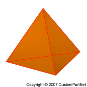
Pyramid |
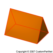
Prism |
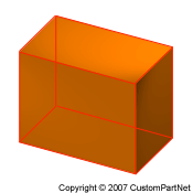
Cuboid |
Other basic 3D shapes include curved surfaces.
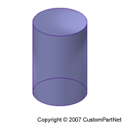
Cylinder |
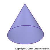
Cone |
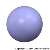
Sphere |
Part Shapes
The 3D shapes of real-world parts typically do not resemble the simple shapes previously shown. They are often highly complex and include numerous contoured surfaces and features. However, any 3D shape can be classified as some basic shape that it most closely remsembles. This is useful for identifying a compatible manufacturing process that is best suited for a given 3D shape. One method of classifying parts is using the following 7 categories:
The 3D shapes of real-world parts typically do not resemble the simple shapes previously shown. They are often highly complex and include numerous contoured surfaces and features. However, any 3D shape can be classified as some basic shape that it most closely remsembles. This is useful for identifying a compatible manufacturing process that is best suited for a given 3D shape. One method of classifying parts is using the following 7 categories:
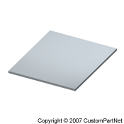
- Flat - Most suitable for sheetmetal forming, but flat plastic parts can be molded.
Basic shape |
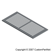
Example: Sheetmetal vent |
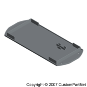
Example: Molded lid |
- Thin-walled: Cylindrical - Metal parts typically machined using turning, while plastic parts are molded. For some simple parts (metal or plastic), extrusion can be used.
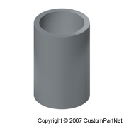
Basic shape |
Example: Turned part |
Example: Molded cover |
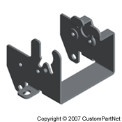
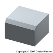
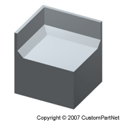
- Thin-walled: Cubic - Metal parts typically machined using milling or formed from sheetmetal, while plastic parts are molded. For some simple parts (metal or plastic), extrusion can be used.
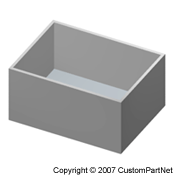
Basic shape |
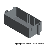
Example: Molded box |
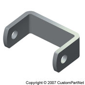
Example: Sheetmetal bracket |
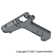
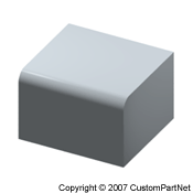
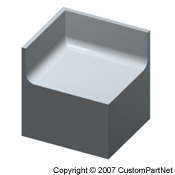
- Thin-walled: Complex - Complex parts are typically formed using molding/casting processes, but can also be formed from sheetmetal.
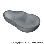
Basic shape |
Example: Molded housing |
Example: Sheetmetal support |
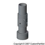
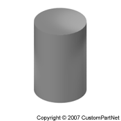
- Solid: Cylindrical - Metal parts typically machined using turning or formed using casting. Solid plastic parts can be molded if they are small. For some simple parts (metal or plastic), extrusion can be used.
Basic shape |
Example: Turned part |
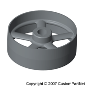
Example: Cast pulley |
- Solid: Cubic - Metal parts typically machined using milling or formed using casting. Solid plastic parts can be molded if they are small. For some simple parts (metal or plastic), extrusion can be used.
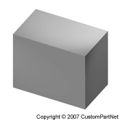
Basic shape |
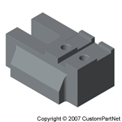
Example: Milled toolholder |
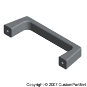
Example: Cast handle |
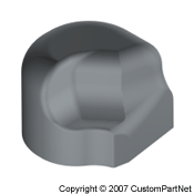
- Solid: Complex - Complex parts are typically formed using casting, forging, or machining. Solid plastic parts can be molded if they are small. processes
Basic shape |
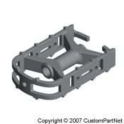
Example: Cast pedal |
Example: Milled part |
Aspect ratio
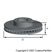
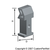
The aspect ratio of a part is another way to characterize the part's shape. The aspect ratio can be measured in different ways, but typically describes the ratio of the part's height to its width. Therefore, a part with a high aspect ratio is tall and thin, while a part with a low aspect ratio is short and wide.
For cylindrical parts, the aspect ratio can be calculated as the height divided by the diameter.
For cubic, or more complex parts, the aspect ratio is often calculated as the height divided by the diagonal between the length and width. The diagonal is used because it accounts for both the length and width of the part.
The aspect ratio of a part is another way to characterize the part's shape. The aspect ratio can be measured in different ways, but typically describes the ratio of the part's height to its width. Therefore, a part with a high aspect ratio is tall and thin, while a part with a low aspect ratio is short and wide.
For cylindrical parts, the aspect ratio can be calculated as the height divided by the diameter.
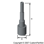
High aspect ratio part |
Low aspect ratio part |
For cubic, or more complex parts, the aspect ratio is often calculated as the height divided by the diagonal between the length and width. The diagonal is used because it accounts for both the length and width of the part.
High aspect ratio part |
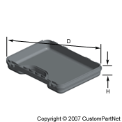
Low aspect ratio part |
Cross section
Identifying the cross sections of a part are useful in both the design and manufacture of many parts. A cross section is the surface that results from slicing a part by a plane. For most parts, the cross section will be different depending on the location and orientation of the slice. However, some simple parts have a uniform cross-section along one or more axes.
Identifying the cross sections of a part are useful in both the design and manufacture of many parts. A cross section is the surface that results from slicing a part by a plane. For most parts, the cross section will be different depending on the location and orientation of the slice. However, some simple parts have a uniform cross-section along one or more axes.
Uniform cross section |
Non-uniform cross section |
Part Features
Features
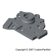
Most parts have a main solid body with numerous features that modify its shape. These features can usually be classified as depressions in the part or protrusions from the surface. There are also angles or curves that can be applied to the part. The types of features on a part often dictate which manufacturing processes can be used to form the part. However, sometimes one process will be used to form the main body of the part and additional operations will be used form the more complex features. When a feature is not formed by the primary process, it is typically referred to as a secondary feature.
Most parts have a main solid body with numerous features that modify its shape. These features can usually be classified as depressions in the part or protrusions from the surface. There are also angles or curves that can be applied to the part. The types of features on a part often dictate which manufacturing processes can be used to form the part. However, sometimes one process will be used to form the main body of the part and additional operations will be used form the more complex features. When a feature is not formed by the primary process, it is typically referred to as a secondary feature.
Cast housing with highlighted features
Depressions: Holes
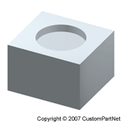
A hole is a depression in a part with a uniform cross section along its depth and a high aspect ratio. In other words, the depression is deeper than it is wide. Most holes have a circular cross-section and form a cylindrical hole. However, a hole can have a polygonal or even an irregular cross-section.
Holes are also characterized by their depth. A hole that extends to any depth inside the part is referred to as a blind hole. A hole that extends completely through the part is known as a through hole. Also, if a hole is cylindrical (regardless of its depth) it may be threaded to allow for another part to be secured to that feature.
Holes can also occur along any axis. For ease of manufacture, holes are typically oriented vertically, or sometimes horizontally. Angled holes can be formed, but are rarely used in the design of a part.
A hole is a depression in a part with a uniform cross section along its depth and a high aspect ratio. In other words, the depression is deeper than it is wide. Most holes have a circular cross-section and form a cylindrical hole. However, a hole can have a polygonal or even an irregular cross-section.
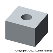
Cylindrical hole |
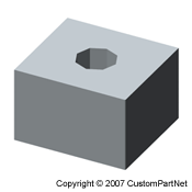
Polygonal hole |
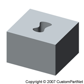
Irregular hole |
Holes are also characterized by their depth. A hole that extends to any depth inside the part is referred to as a blind hole. A hole that extends completely through the part is known as a through hole. Also, if a hole is cylindrical (regardless of its depth) it may be threaded to allow for another part to be secured to that feature.
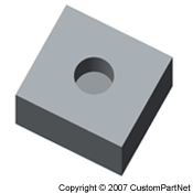
Blind hole |
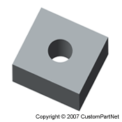
Through hole |
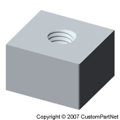
Threaded hole |
Holes can also occur along any axis. For ease of manufacture, holes are typically oriented vertically, or sometimes horizontally. Angled holes can be formed, but are rarely used in the design of a part.
Depressions: Slots
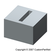
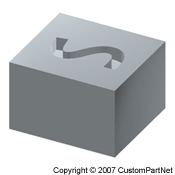
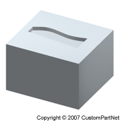
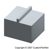
A slot is a depression in a part with a uniform cross-section along its length and is far longer than it is wide or deep. The cross-section of a slot can have a variety of shapes.
A slot does not necessarily have to follow a straight path. It can also follow a simple curve or any complex path.
Lastly, the location of a slot in a part can vary greatly. The slot can be completely contained within all sides of the part, or it can extend to one or more sides. Also, the depth of the part can extend through the part.
A slot is a depression in a part with a uniform cross-section along its length and is far longer than it is wide or deep. The cross-section of a slot can have a variety of shapes.
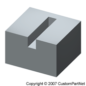 Rectangular slot |
 Semi-circular slot |
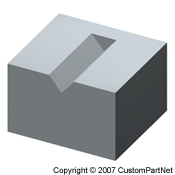 V slot |
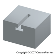 T slot |
A slot does not necessarily have to follow a straight path. It can also follow a simple curve or any complex path.
Straight path |
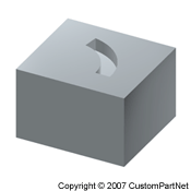
Curved path |
Complex path |
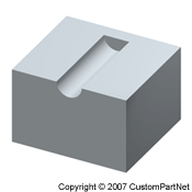
Lastly, the location of a slot in a part can vary greatly. The slot can be completely contained within all sides of the part, or it can extend to one or more sides. Also, the depth of the part can extend through the part.
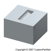
Contained slot |
4 types of partial slots |
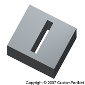
Through slot |
Depressions: Pockets
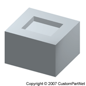
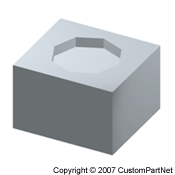
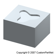
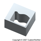
A pocket is a depression that does meet the criteria to be considered a hole or a slot. If a feature has a uniform cross section along its depth, but has a low aspect ratio it is considered a pocket, not a hole. Also, a feature with a high aspect ratio but a non-uniform cross-section is also a pocket, not a hole.
A feature with a uniform cross section along its length that is not very long is considered a pocket, not a slot. Also, a feature that is sufficiently long but has a non-uniform cross-section along its length is considered a pocket, not a slot.
As seen in the above examples, a pocket can have a uniform or non-uniform cross section along any direction. As with holes and slots, the cross-section of a pocket can be a regular polygon, or any irregular shape. Also, a pocket does not necessarily require a flat base. In fact, a pocket will typically have a contoured base. When a pocket combines many of the elements described above, such as an irregular and non-uniform cross-section and a contoured base, it can take on a highly complex form.
Lastly, much like a slot, a pocket can be located on the part in a variety of ways. Most pockets, like those shown above, are contained within the main body of the part. However, a pocket can also extend to one or several surfaces of a part.
A pocket is a depression that does meet the criteria to be considered a hole or a slot. If a feature has a uniform cross section along its depth, but has a low aspect ratio it is considered a pocket, not a hole. Also, a feature with a high aspect ratio but a non-uniform cross-section is also a pocket, not a hole.
Low aspect ratio pocket, not a hole |
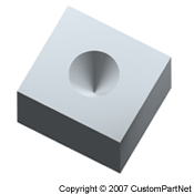
Non-uniform pocket, not a hole |
A feature with a uniform cross section along its length that is not very long is considered a pocket, not a slot. Also, a feature that is sufficiently long but has a non-uniform cross-section along its length is considered a pocket, not a slot.
Wide pocket, not a slot |
Non-uniform pocket, not a slot |
As seen in the above examples, a pocket can have a uniform or non-uniform cross section along any direction. As with holes and slots, the cross-section of a pocket can be a regular polygon, or any irregular shape. Also, a pocket does not necessarily require a flat base. In fact, a pocket will typically have a contoured base. When a pocket combines many of the elements described above, such as an irregular and non-uniform cross-section and a contoured base, it can take on a highly complex form.
 Regular cross section |
 Irregular cross section |
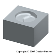 Contoured base |
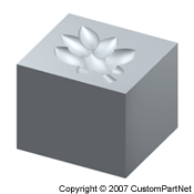 Highly complex pocket |
Lastly, much like a slot, a pocket can be located on the part in a variety of ways. Most pockets, like those shown above, are contained within the main body of the part. However, a pocket can also extend to one or several surfaces of a part.
2 types of partial pockets |
Through pocket |
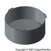
Depressions: Captured cavities
A captured cavity is a pocket with inward curving surfaces, often called reentrant surfaces. If a solid object were to fill such a cavity, it could not be removed. Many manufacturing processes are incapable of producing parts with such a feature. A variation on a captured cavity is an enclosed cavity, in which the pocket is surrounded on all sides by surfaces of the part. There are very few manufacturing processes that can form an enclosed cavity in a part. The easiest way to form an enclosed cavity is by joining two or more parts together.
A captured cavity is a pocket with inward curving surfaces, often called reentrant surfaces. If a solid object were to fill such a cavity, it could not be removed. Many manufacturing processes are incapable of producing parts with such a feature. A variation on a captured cavity is an enclosed cavity, in which the pocket is surrounded on all sides by surfaces of the part. There are very few manufacturing processes that can form an enclosed cavity in a part. The easiest way to form an enclosed cavity is by joining two or more parts together.
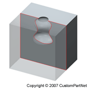
Captured cavity |
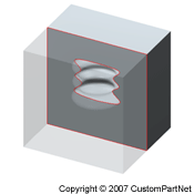
Enclosed cavity |
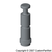
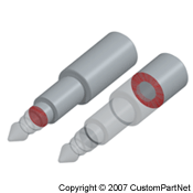
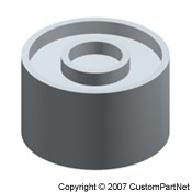
Protrusions: Bosses
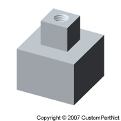
A boss is a protrusion on a part with a high aspect ratio. In a sense, it is the inverse of a hole, but does not necessarily require a uniform cross-section. Most bosses have a circular cross-section and form a cylindrical boss. However, a boss can have a polygonal, irregular, or any non-uniform cross-section.
Bosses are often times designed with a hole in the center, forming a hollow boss. Much like the boss itself, the hole can have a variety of shapes. Another type of boss, is a threaded boss, which can be a cylindrical boss with external threads or any boss with a threaded cylindrical hole.
Bosses can occur along any axis, but for ease of manufacture, are typically oriented vertically or horizontally. However, angled bosses are sometimes used.
A boss is a protrusion on a part with a high aspect ratio. In a sense, it is the inverse of a hole, but does not necessarily require a uniform cross-section. Most bosses have a circular cross-section and form a cylindrical boss. However, a boss can have a polygonal, irregular, or any non-uniform cross-section.
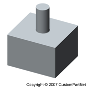
Cylindrical boss |
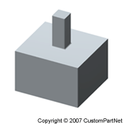
Square boss |
 Irregular boss |
Non-uniform boss |
Bosses are often times designed with a hole in the center, forming a hollow boss. Much like the boss itself, the hole can have a variety of shapes. Another type of boss, is a threaded boss, which can be a cylindrical boss with external threads or any boss with a threaded cylindrical hole.
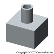
Hollow boss |
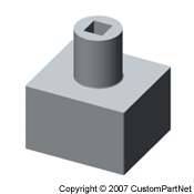
Hollow boss |
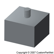
Threaded boss |
Threaded boss |
Bosses can occur along any axis, but for ease of manufacture, are typically oriented vertically or horizontally. However, angled bosses are sometimes used.
Protrusions: Ribs
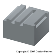
A rib is a protrusion on a part with a uniform cross section along its length and is far longer than it is wide or deep. A rib can be described as the inverse of a slot and can similarly have a variety of shapes.
Much like slots, ribs can be designed to follow a straight path or a curved path. Also, ribs are often designed in a series or pattern. Several common arrangements of ribs are shown below.
A rib is a protrusion on a part with a uniform cross section along its length and is far longer than it is wide or deep. A rib can be described as the inverse of a slot and can similarly have a variety of shapes.
Rectangular rib |
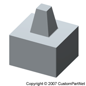
Trapezoidal rib |
Much like slots, ribs can be designed to follow a straight path or a curved path. Also, ribs are often designed in a series or pattern. Several common arrangements of ribs are shown below.
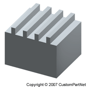
Uni-directional ribs |
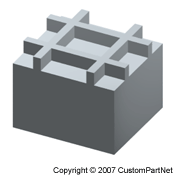
Multi-directional ribs |
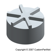
Radial ribs |
Circumferential ribs |
Protrusions: Steps
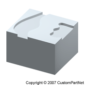
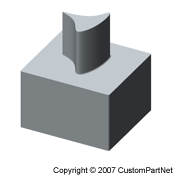
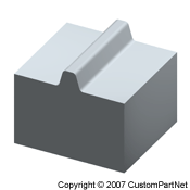
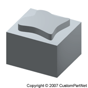
A step is a protrusion on a part that has a low aspect ratio. In other words, the feature is wider than it is tall. A step can have a variety of cross sections and they can be uniform or non-uniform along any direction. Also, a step can be a flat surface or a contoured shape. When a step combines many of the elements described above, such as an irregular and non-uniform cross section and a contoured top, it can take on a highly complex form.
A step is a protrusion on a part that has a low aspect ratio. In other words, the feature is wider than it is tall. A step can have a variety of cross sections and they can be uniform or non-uniform along any direction. Also, a step can be a flat surface or a contoured shape. When a step combines many of the elements described above, such as an irregular and non-uniform cross section and a contoured top, it can take on a highly complex form.
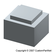
Regular step |
Irregular step |
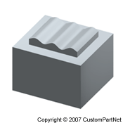
Contoured step |
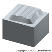
Highly complex step |
Protrusions: Gussets
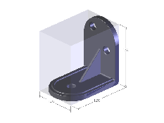
A gusset is a triangularly shaped protrusion that connects two surfaces to offer additional support. A gusset is typically used between a wall of a part and the flat surface from which it protrudes. Gussets are also used to support other features, such as bosses, ribs, and steps.
A gusset is a triangularly shaped protrusion that connects two surfaces to offer additional support. A gusset is typically used between a wall of a part and the flat surface from which it protrudes. Gussets are also used to support other features, such as bosses, ribs, and steps.
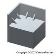
Wall gussets |
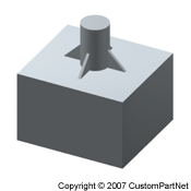
Boss gussets |
Angles
Some part features are not depressions or protrusions on the part surface, but rather angles and curves of the surface. Such features include the following:
Some part features are not depressions or protrusions on the part surface, but rather angles and curves of the surface. Such features include the following:
- Chamfer - An angled surface in place of the edge where two surfaces meet. Most chamfers are 45 degrees and occur between two perpendicular surfaces. However, a chamfer can be designed for any angle between any two adjacent surfaces. Also, a chamfer can occur on either the exterior or interior of the part.
External chamfer |
Internal chamfer |
- Fillet - A fillet is similar to a chamfer but the surface is curved, rather than flat. Just like a chamfer, a fillet can be external or internal. Fillets are commonly used where a feature meets the main body of the part.
External fillet |
Internal fillet |
- Draft - Draft is a slight angle that is applied to walls and other features of a part. In molding and casting processes, a draft angle is often required on the surfaces of a part that are parallel to the tooling direction in order to facilitate removal from the mold.
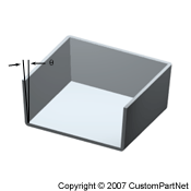
Drafted part |
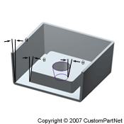
Drafted features |
- Bend - A bend, where an angle change occurs in the main body of a part, is a common feature of parts made from sheetmetal or long bars or tubes.
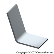
Sheetmetal bend |
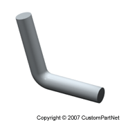
Bar bend |
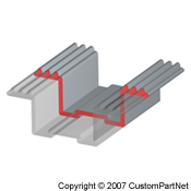
Multi-axis features
All of the above features (holes, slots, pockets, bosses, ribs, steps, etc.) can occur along any axis. Typically, all features on a part occur along the same axis because it will be easier to manufacture. Whether the features are made by a mold, machining tool, sheetmetal blank, or other device, a single axis means the tool will always move in the same direction, referred to as the tooling direction. Multi-axis features require additional tooling directions which will add time and cost to the manufacture of the part. In molding and casting processes, features that are not along the tooling direction are referred to as undercuts and can occur externally or internally.
All of the above features (holes, slots, pockets, bosses, ribs, steps, etc.) can occur along any axis. Typically, all features on a part occur along the same axis because it will be easier to manufacture. Whether the features are made by a mold, machining tool, sheetmetal blank, or other device, a single axis means the tool will always move in the same direction, referred to as the tooling direction. Multi-axis features require additional tooling directions which will add time and cost to the manufacture of the part. In molding and casting processes, features that are not along the tooling direction are referred to as undercuts and can occur externally or internally.
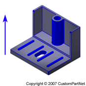
Uni-axial features |
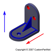
Multi-axis features |
Part Parameters
Coming soon