B
Bar advance time
When a bar feeder is used as the fixture, one piece of bar stock is loaded and simply advanced into position before each cycle, rather than loading a new workpiece. The bar advance time is the amount of time (in minutes) required to advance the bar into position for the next part to be machined.
Bar end
The material at the end of a piece of bar stock that will not be used. The bar end, or bar remnant, is typically the result of a device holding the bar while the stock is cut. The bar end is used in determining how many workpieces a single piece of bar stock will yield.
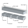
Bar stock |
Bar load time
When a bar feeder is used as the fixture, one piece of bar stock is loaded and simply advanced into position before each cycle, rather than loading a new workpiece. The bar load time is the amount of time (in minutes) required to load the bar, which occurs everytime the number of workpieces per bar have been machined.
Bases
Structures that act as the bottom support for other parts. (Includes: feet, foundations, pedestals, platforms, shelves, stands, structures, supports, trays, etc)
Beams
Long, rigid structures that are attached at one or both ends to a surface to provide support. (Includes: arms, axles, bars, columns, cylinders, pillars, poles, posts, rails, rods, shafts, spokes, structures, struts, supports, trusses, etc)
Bend allowance
The length of the neutral axis between the bend lines, or in other words, the arc length of the bend. The bend allowance added to the flange lengths is equal to the total flat length.

Bending diagram |

Neutral axis |
Bend angle
The angle to which a piece of material has been bent. The bend angle can be measured between the bent material and its original position, or as the included angle between perpendicular lines drawn from the bend lines.

Bending diagram |
Bend deduction
The bend deduction, sometimes called the bend compensation, describes the amount a piece of material has been stretched by bending. The value equals the difference between the mold line lengths and the total flat length. The mold line lengths are the distances measured to the outside mold line and are equal to the flange lengths plus the setback.

Bending diagram |
Bending force
The amount of force required to bend a piece of material into a new permanent shape. The bending force must create enough stress in the material to exceed the yield strength, allowing the material to plastically deform. In bending, the applied force will cause tension on side of the material and compression on the other.

V bending |

Wipe bending |
Bend length
The length of a bend formed in a piece of sheet metal. This length is measured along the bend axis, which is typically a straight line.

Bending diagram |
Bend radius
The radius of a bend in a piece of material that occurs between the bend lines. The radius is measured from the bend axis to the inside surface of the material and is therefore sometimes specified as the inside bend radius. The bend radius is typically equal to at least the sheet thickness.

Bending diagram |
Blank
A piece of sheet metal that is used as an initial workpiece on which other sheet metal operations will be performed. Blanks are cut from a larger piece of sheet stock in the blanking process and typically have a simple geometric shape, such as a rectangle or circle.

Rectangular blanks |

Round blanks |
Boss
A cylindrical protrusion on a part that is used for aligning or fastening another part by accepting a screw or other insert through a hole in the center.
Box type
The type of box recommended for packing may be a corrugated cardboard box or a wood crate. Corrugated cardboard boxes are characterized by their wall thickness and test strength, which both determine the maximum weight the box can hold. The test strength listed here is the bursting strength measured in pounds per square inch.
Brackets
Structures that can be fastened between two adjacent surfaces to provide support. (Includes: braces, hinges, structures, supports, etc)
Brinell Hardness Test
ASTM E10. A common standard method of measuring the hardness of metallic materials. A hardened steel or tungsten carbide ball is pressed into the smooth surface of the material with a specific load. A microscope in used to measure the diameter of the indentation in the material surface and then compared to the corresponding Brinell Hardness Number (BHN) on a chart or calculated from a prescribed formula, the applied load in kilograms divided by the surface area of the resulting impression in square millimeters. The Brinell hardness test for steel involves impressing a 10 mm diameter hardened steel or tungsten carbide ball with a load of 3000 kilograms. The Vickers hardness scale is preferred for steels with a hardness over 500 BHN.
Build speed
In additive fabrication processes, a part is built by adding layers of material upon one another. The build speed refers to how fast the part can be fabricated in this way and depends upon the specific process and equipment being used. Build speed can be measured as the amount of area in one layer built in a given time (X-Y direction), the number of layers built in a given time (Z direction), or as a volumetric rate.
Back to top

