S
Scallop
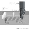
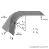
In an end milling operation, a small cusp of material, called a scallop, sometimes remains between adjacent cuts. Scallops along vertical walls can be removed through a profiling operation. Scallops on horizontal surfaces result from using a ball end mill and can be minimized by using a smaller step-over distance relative to the tool diameter.
Scallop |
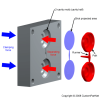
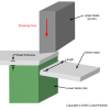
Separating force
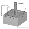
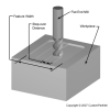
The outward force exerted on the mold halves caused by the injection of molten material during the mold filling stage. The separating force is the product of the cavity pressure and the projected area of the shot. The clamp force applied to the mold must be greater than this separating force in order to keep it securely closed while the material is injected.
Separating force |
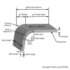
Setback
In bending, the setback refers to the distance from the bend line to the outside mold line.
Bending diagram |
Setup time
The amount of time required to setup a process before production begins. The setup time may include the preparation of the material, machine, and tooling, as well as any testing or calibration that is needed.
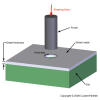
Shearing force
The amount of force required to cut or remove a piece of material through shear, as is done in cutting, blanking or punching operations. The applied force must create enough shear stress in the material to exceed the ultimate shear strength, causing the material to fail and separate.
Shearing |
Punching |
Shear strength
The amount of shear stress a material can sustain, measured in units of force per unit area. Shear strength is commonly expressed as megapascals (MPa) or pounds per square inch (psi) of original cross section. The maximum shear stress that a material can withstand before eventually failing is called the ultimate shear strength.
Sheet border
The sheet border, or stock border, refers to the space between the edge of a piece of sheet stock and the blanks or parts closest to the edge that will be cut. This border may be different along the length and width of the sheet. After all parts have been cut, the sheet border will remain as scrap material. The sheet border is used in determining how many parts a single piece of sheet stock will yield.
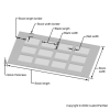
Sheet stock (Rectangular blanks) |
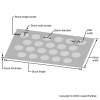
Sheet stock (Round blanks) |
Shot
The amount of material that is injected or poured into a mold. The shot volume includes the volume of all part cavities, as well as the feed system which delivers the material. The amount of material forming the parts relative to the total shot volume is the material yield. The shot volume must be less than the shot capacity of the machine being used. The projected area of the shot describes the projected area of all mold space that fills with material.
Shrinkage
When a part is formed from molten material, the part will shrink as the material cools and solidifies. As a result, a shrinkage allowance is usually added to the size of the part.
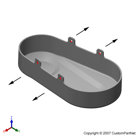
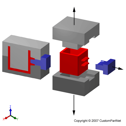
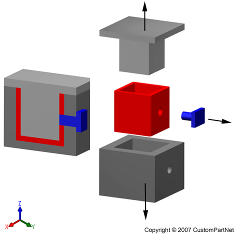
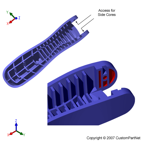
Side-action
An additional mold device, such as a side-core, that is actuated through one of the four sides of the mold. One or more side-actions can act through any of the four sides of the mold. The number of sides with such a device, referred to as side-action directions, limits the number of possible cavities in the mold.

4 side-actions in 2 directions |
Sink marks
When molten material is injected into a mold, voids can occur if certain sections solidify first, caused by a low injection pressure or non-uniform wall thickness. The remaining material will fill these voids as it continues to cool and shrink. This shrinkage causes marks on the part where the material sunk into the void.
Spacers
Components that are placed between a fastener and a part to create a more precise or secure fit. (Includes: bushings, collars, grommets, rings, seals, sleeves, washers, etc)
Specific cutting energy
The amount of energy per unit volume to remove material from the workpiece during a machining operation, measured in horsepower per cubic inches per minute. The specific cutting energy, also known as unit power, is a material property but is also affected by the type of machining operation and the material and sharpness of the cutting tool. Values for specific cutting energy are typically in the range of 0.1 -2.5 hp/in^3/min (most steels have a value of 1.0-1.5 hp/in^3/min).
Specific heat
Specific heat capacity, or just specific heat, is the amount of energy that is required to raise the temperature of a given amount of material by one degree, typically measured in J/g-K or BTU/lb-F.
Speed control
In some turning operations, the diameter of the workpiece changes so the spindle speed (RPM) and cutting speed (SFM) can not both remain constant. Constant RPM will cause the cutting speed to decrease as the tool moves towards the center of the workpiece. In order to maintain constant SFM, the RPM is increased as the diameter decreases.
Spindle horsepower
The power required from the spindle to rotate a cutting tool (milling machine) or workpiece (turning machine) during a machining operation. The spindle horsepower is typically less than the machine's motor horsepower due to the machine efficiency being less than 100%.
Spindle speed
The rotational speed of the spindle in revolutions per minute (RPM). In a milling machine, the spindle speed describes the rotation of the attached cutting tool. In a turning machine, it describes the rotation of the attached workpiece.
Spindle torque
The torque produced by the spindle based upon the spindle horsepower and the spindle speed at which it is rotating.
Springback
In bending, residual stresses cause the material to spring back slightly after the bending operation. Due to this elastic recovery, it is necessary to over-bend a precise amount to achieve the desired bend radius and bend angle. The final bend radius will be greater than initially formed and the final bend angle will be smaller. The ratio of the final bend angle to the initial bend angle is defined as the springback factor, Ks. The amount of springback depends upon several factors, including the material, bending operation, and the initial bend angle and bend radius.
Springback |
Sprue
The main channel through which molten material enters a mold. The sprue often connects to a series of runners that deliver the material into the mold cavities.
Stainless Steel
Strictly speaking, stainless steel is a trade name, an alloy originally patented in 1916 by English metallurgist Harry Brearley, containing a maximum of 0.70% carbon and 9-16% chromium. In the United States, American Stainless Steel Co. of Pittsburgh, PA, produces a chrome-iron alloy under the "stainless steel" patent which it owns. In more general terms, stainless steel is a corrosion resistant steel containing at least 10% chromium. According to the American Iron and Steel Institure (AISI), a steel is considered "Stainless" if it contains 4% or more chromium. Stainless Steels are characterized by their resistance to organic acids, weak mineral acids, and atmospheric oxidation, and their ability to retain their strength at high temperatures. The most common grades of stainless steel in the US are: Type 304, austenitic (chromium-nickel); Type 316, austenitic with 2%-3% molybdenum; Type 409, ferritic (low chromium) for high-temperature use; Type 410, heat-treatable martensitic (medium chromium) with a high strength level; and Type 430, a ferritic general-purpose grade with some corrosion resistance.
Step-over distance
In order to machine a feature that is wider than the width of a single cut, the tool must make several cuts, stepping to the side after each one. This step-over distance is equal to the radial depth of cut for each cut and must be less than or equal to the tool diameter. The size of the step-over distance will determine the scallop height between each step.
Peripheral cut |
Slot cut |
Stock utilization
The percentage of material from a piece of stock that is used as a workpiece/blank or final part. When cutting from a piece of stock, any material left attached to the stock or lost in the cutting process is considered scrap. Such scrap material includes the sheet border and web width in the case of sheet stock, and the bar end and cutoff width in the case of bar stock.
Storage containers
Large containers that are used for storing multiple items. (Includes: baskets, bins, boxes, cases, containers, crates, drawers, receptacles, etc)
Stress
Force per unit area. True stress denotes stress determined by measuring force and area at the same time. Conventional stress, as applied to tension and compression tests, is force divided by original area. Nominal stress is stress computed by simple elasticity formula. It can be divided into components, normal and parallel to the plane, called normal stress and shear stress, receptively. Nominal stress, ignoring stress raisers and disregarding plastic flow, in a notch bend test, for example, it is bending moment divided by minimum section modulus. See also residual stress.
Stress Strain Curve
A graph in which stress (load divided by the original cross sectional area of the test piece) is plotted against strain (the extension divided by the length over which it is measured). The slope of the sress strain curve, in the elastic region, is used to determine the modulus of elasticity.
Structural elements
Parts whose primary function is to form the shape of a product and/or support the weight of other parts.
Surface area
The total area of all surfaces that compose a part.
Surface patch
A portion of a part’s surface that is either flat or smoothly curved. The boundary of a surface patch is a sharp corner or curve, where another surface patch begins. The number of surface patches that comprise a part is an indication of the part’s complexity.
Surface roughness
The roughness of a part's surface resulting from a manufacturing process. Surface roughness is typically measured as the arithmetic average (Ra) or root mean square (RMS) of the surface variations, measured in microinches or micrometers. A typical primary manufacturing process results in an Ra surface roughness of 32-250 microinches and finishing operations can lower the roughness to 1-32 microinches.
Switches
Small interfaces that are designed to be pushed or rotated by the user’s fingers or hand. (Includes: buttons, dials, knobs, triggers, wheels, etc)
Back to top